Model Reference: Pin Configurations
The Reconfigurable Circuits extension of the amoebot model introduces a new communication system that allows amoebots to communicate using configurable structures called circuits. This page describes how this communication system is represented in the simulation environment and how it is used.
Pin Configuration Overview
The basic component of the circuit communication system is the pin. Each algorithm specifies the number of pins \(k\) used by the amoebots. This means that every amoebot will have \(k\) pins on each of its incident edges. Thus, contracted amoebots have \(6k\) pins and expanded amoebots have \(10k\) pins overall.
The pins of two amoebots incident to the same edge are connected in pairs called external links. Each link contains one pin of each amoebot. This allows the amoebots to use each pair of connected pins as a communication channel.
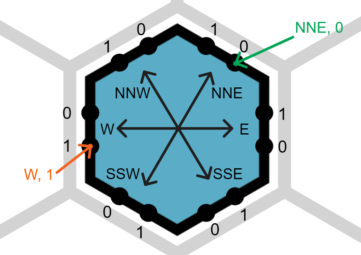
On each edge incident to an amoebot, the pins are numbered \(0,\ldots,k-1\) in the local counter-clockwise direction of the amoebot. This numbering is internal: Other amoebots may not have the same numbering and cannot see the numbering of a neighbor directly. Due to the way the pins of neighboring amoebots are connected, we can see how their pin numberings relate to each other:
- If the amoebots have the same chirality, pin \(0\) of one amoebot will be connected to pin \(k-1\) of the neighbor, pin \(1\) to \(k-2\), etc. In other words, the pin numberings of the neighbors are the exact opposite of each other.
- If the amoebots have a different chirality, the pins will share the same numbering.

Partition Sets
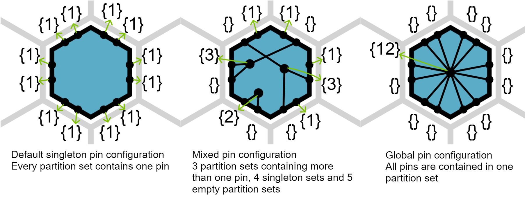
The external links between the pins of different amoebots are established automatically as soon as the amoebots become neighbors. However, an amoebot can also connect its own pins internally, causing them to behave like a single pin with multiple external connection points. If any of the pins sends or receives a beep, all of them will do the same. Any number of pins can be connected in this way. We call a maximal set of connected pins a partition set. If a pin is not connected (internally) to any other pins, we call its partition set a singleton.
In the mathematical model, the partition sets of an amoebot are defined as disjoint sets of pins such that each pin is contained in a partition set. The model does not contain any assumption or restriction on the number of partition sets since it even allows empty partition sets. We use this feature of the model to implement partition sets in the simulator: Note that the maximum number of non-empty partition sets is equal to the total number of pins (i.e., one pin in each partition set). Thus, a contracted amoebot needs at most \(6k\) partition sets and an expanded amoebot will need at most \(10k\) partition sets. In our approach, we simply give an amoebot the maximum number of partition set objects it may require. The amoebot cannot add or remove partition sets manually, the number only changes when the amoebot expands or contracts. All it can do is assign its pins to the partition sets: Every pin belongs to exactly one of the partition sets at any time. If the amoebot has \(m\) partition sets, the sets are identified by the indices \(0,\ldots,m-1\). However, the index of a partition set does not have any implications regarding its content. We only use the numbering to easily refer to individual partition sets.
The pin configuration of an amoebot is the set of its partition sets. It defines how the amoebot's pins are connected internally. In a singleton pin configuration, all partition sets are singletons, i.e., there are no internal connections between any pins. In a global pin configuration, all pins are contained in the same partition set.

Partition sets with more than one pin are visualized as black circles inside the amoebots that are connected to the contained pins with thin lines (see image above). Each pair of curly brackets in the image represents one partition set. The numbers inside the curly brackets specify the number of pins contained in a partition set. Note that there are \(6k = 12\) partition sets because \(k = 2\) and the amoebot is contracted. The partition set IDs range from \(0\) to \(11\) but are not shown in the picture.
Circuits
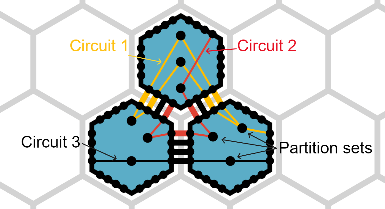
If two partition sets of neighboring amoebots contain a pair of connected pins, we say that the partition sets are connected. A maximal set of connected partition sets is called a circuit. We say that an amoebot is on the circuit if one of its partition sets is contained in the circuit. If any amoebot on the circuit sends a beep on a partition set in the circuit, all partition sets in the circuit will receive a beep. Note that a circuit can contain multiple partition sets of the same amoebot, causing them to behave as if they were one set. If a circuit contains at least one partition set of each amoebot, i.e., all amoebots are on the circuit, we call it a global circuit. An easy way to establish a global circuit is to give each amoebot a global pin configuration.

In the simulator, circuits are indicated by different colors where possible.
Implementation
In the simulation environment, an amoebot's pin configuration is represented by an instance of the PinConfiguration class.
This class contains all pins and partition sets of an amoebot as instances of the Pin and PartitionSet classes, and it simply identifies them with integer IDs.
A PinConfiguration instance is always specific to an expansion state, which also defines the range of the IDs:
It is \(0,\ldots,6k-1\) if the configuration is contracted and \(0,\ldots,10k-1\) if it is expanded.
A contracted PinConfiguration instance is incompatible with an expanded PinConfiguration in the sense that the same IDs may not refer to the same pins.
Similarly, expanded instances with different expansion directions are also incompatible.
It is possible for partition set instances to be empty, e.g., if the partition set with ID 0 contains all pins, then all other partition sets will automatically be empty.
Individual pins are addressed by a combination of the edge on which a pin is located and the pin's index on that edge. The index is in the range \(0,\ldots,k-1\) and comes from the local pin numbering of the amoebot. The image below shows an amoebot with its internal compass and pin numbering. The two highlighted pins are identified by a combination of local direction and edge index. For expanded amoebots, a third parameter is necessary to distinguish between the amoebot's head and tail.

Reading Pin Configurations
The GetCurrPinConfiguration method returns the pin configuration from the beginning of the current phase.
If the amoebot has received any beeps or Messages in the previous beep phase, they can be read using the returned PinConfiguration instance or directly in the algorithm code, without the instance.
To check for received beeps, the ReceivedBeepOnPartitionSet and ReceivedBeepOnPin methods can be called, giving the partition set ID or pin location as parameter, or the ReceivedBeep method can be called directly on a PartitionSet or Pin instance.
Similar methods exist to check for messages.
As outlined in the Round Simulation reference, this will always work in the movement phase. In the beep phase, the received beeps and messages can only be read if the amoebot has not performed a movement in the previous movement phase. If a movement was performed, the amoebot's pin configuration is automatically reset to a singleton configuration and the received beeps and messages are lost. Note that the circuit on which a beep or message was sent may not exist anymore after the movement phase, even if the amoebot itself did not perform any movements. The ability to still read the received information is a convenience functionality to avoid having to store this information manually.
Changing Pin Configurations and Sending Beeps
An amoebot can change its pin configuration in the beep phase.
To do so, it modifies the PinConfiguration instance defining the next configuration.
This instance can be obtained by calling the GetNextPinConfiguration method, after which it can be modified freely.
Another way to change it is to call SetNextPinConfiguration(PinConfiguration pc), which will overwrite the next pin configuration to pc.
The PinConfiguration instance pc must match the amoebot's expansion state.
This instance can either be the current pin configuration or a new one created using Get<Contracted|Expanded>PinConfiguration.
Any PinConfiguration instance can be modified in several ways:
SetToGlobal(int id)collects all pins in the partition set with IDidSetStarConfig(int offset, int id)collects all pins with edge indexoffsetin the partition set with IDid. This partition set will contain exactly one pin from each edge. The method has several overloads for selecting the pins more flexibly.MakePartitionSet(int[] pinIds, int id)puts the pins specified by thepinIdsarray into the partition set with IDid. This method can be used to create any desired partition set.
Note that SetNextPinConfiguration replaces the pin configuration planned for the next round, so the instance obtained by GetNextPinConfiguration is useless afterwards.
Call SendBeepOnPartitionSet(int id) to send a beep on the partition set with ID id and SendBeepOnPin(Direction d, int offset) to send a beep on the pin at the given position.
Similarly to reading received beeps, you can send beeps by calling the corresponding methods directly on the PartitionSet or Pin instances contained in the next PinConfiguration.
The same works for messages.
For example, the following code shows how to set up any of the three pin configurations shown in the second figure above (assuming compass direction E and counter-clockwise chirality):
public override void ActivateBeep() {
    PinConfiguration pc = GetCurrPinConfiguration();  // Gets the current pin configuration object

    // ----- Setup the first (singleton) pin configuration -----
    pc.SetToSingleton();

    // ----- Setup the second (mixed) pin configuration -----
    // Choosing partition sets 0, 1 and 2 to contain more than one pin
    // First partition set with 3 pins
    pc.MakePartitionSet(
        new int[] {
            pc.GetPinAt(Direction.NNE, 0).Id,
            pc.GetPinAt(Direction.W, 0).Id,
            pc.GetPinAt(Direction.W, 1).Id
        },
        0  // Partition set with ID 0
    );
    // Second partition set with 3 pins
    pc.MakePartitionSet(
        new int[] {
            pc.GetPinAt(Direction.E, 0).Id,
            pc.GetPinAt(Direction.NNW, 1).Id,
            pc.GetPinAt(Direction.SSE, 0).Id
        },
        1  // Partition set with ID 1
    );
    // Partition set with 2 pins
    pc.MakePartitionSet(
        new int[] {
            pc.GetPinAt(Direction.SSW, 0).Id,
            pc.GetPinAt(Direction.SSW, 1).Id
        },
        2  // Partition set with ID 2
    );

    // ----- Setup the third (global) pin configuration in partition set 0 -----
    pc.SetToGlobal(0);
}
Additional Features
Particles can set the color of a partition set to influence the display color of the circuit containing that partition set.
The method pc.SetPartitionSetColor(int id, Color color) can be called on a PinConfiguration instance pc to set the color of its partition set with ID id.
The pin configuration must be the next pin configuration, otherwise the color override will not be visible.
A circuit will take the color of the first colored partition set that is encountered while computing the circuits.
If no colored partition sets are encountered, the circuit will get a color from the circuit color pool (found in ColorData).
Additionally, the placement of the partition sets inside the amoebot can be defined by setting the placement mode.
This can be done by calling the SetPSPlacementMode(PSPlacementMode mode, bool head) method on a pin configuration.
The PSPlacementMode enum specifies various modes for placing partition sets automatically or manually and the mode can be set individually for an expanded amoebot's head and tail by using the head parameter.
Note that this only works for non-empty partition sets.
If the partition set contains only one pin, the SetPartitionSetDrawHandle(int partitionSetId, bool draw) method must be called with parameter true to ensure that the partition set gets its own handle (this is only drawn automatically for sets with at least 2 pins).
The available placement modes are:
NONE:- Uses the default placement mode and does not override any positions.
LINE:- Distributes the partition sets evenly on a line in the center of the amoebot (or its head or tail if it is expanded). The line will be vertical for contracted amoebots and perpendicular to the expansion direction for expanded amoebots.
LINE_ROTATED:- Similar to
LINE, but the rotation angle can be set manually using theSetLineRotation(float angle, bool head)method.
- Similar to
LLOYD:- Places the partition sets on a circle such that each partition set is close to the average position of its pins but not too close to the other partition sets.
MANUAL:- Places each partition set at a custom position defined using polar coordinates.
The position of a partition set can be defined by calling the
SetPartitionSetPosition(int id, Vector2 polarCoords, bool head)method on aPinConfigurationinstance or theSetPosition(Vector2 polarCoords, bool head)method on aPartitionSetinstance. TheVector2 polarCoordsdefines the angle and distance of the partition set relative to the center of the amoebot. Partition sets for which no position was set will be placed directly in the center.
- Places each partition set at a custom position defined using polar coordinates.
The position of a partition set can be defined by calling the
Pin configurations can also be stored in particle attributes.
The special type of attribute for this purpose is created by the CreateAttributePinConfiguration method, which accepts null as an initial value.
Attributes of this type are not displayed in the UI and cannot be accessed by other amoebots.
Their only purpose is to save complex pin configurations so that they can be reused later without having to construct them again.
Note that stored pin configurations cannot be used to read beeps and messages.
The simulator additionally provides a beep failure feature. If you set the beep failure probability \(p\) to a non-zero value in the configuration file or the Settings Panel, the simulator will randomly cause failures on partition sets, causing a partition set to not receive any beeps or messages for one round with probability \(p\). This feature is explained on the amoebot Model page.