Joint Movements

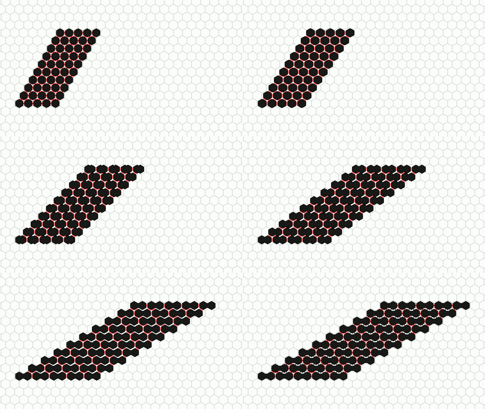
In the basic amoebot model, the maximum distance an amoebot can move per round is a small constant: An amoebot can expand in one round and contract in the next, after which it has moved at most one grid node in any direction. This restriction might limit the speed at which movement or shape formation problems can be solved, especially for larger structures. The joint movement extension adds a mechanism for the amoebots to push and pull each other through so-called bonds, allowing them to cover much greater distances in a single round.
Model Description
The following text and figures are taken from Shape Formation and Locomotion with Joint Movements in the Amoebot Model by Padalkin, Kumar and Scheideler (arXiv, 2023), and were edited to match the model implemented by the simulator.
In the joint movement extension, the way the amoebots move is altered. The idea behind the extension is to allow amoebots to push and pull other amoebots. The necessary coordination of such movements can be provided by the reconfigurable circuit extension (see the previous page for details).
In the following, we formalize and extend the joint movement extension. Let \(S\) denote the set of all amoebots and \(G_S = (S, E_S)\) denote the subgraph of \(G_\Delta\) induced by \(S\). Joint movements are performed in two steps.
In the first step, the amoebots remove bonds from \(G_S\) as follows. Each amoebot can decide to release an arbitrary subset of its currently incident bonds in \(G_S\). A bond is removed iff either of the amoebots at the endpoints releases the bond. However, an expanded amoebot cannot release the bond connecting its occupied nodes. Let \(E_R \subseteq E_S\) denote the set of the remaining bonds, and \(G_R = (S, E_R)\) the resulting graph.
We require that \(G_R\) is connected since otherwise, disconnected parts might float apart. We say that a connectivity conflict occurs iff \(G_R\) is not connected. Whenever a connectivity conflict occurs, the amoebot structure transitions into an undefined state such that we become unable to make any statements about the structure.
Note
In the simulator, transitioning into such an undefined state usually resets the round simulation.

In the second step, each amoebot may perform one of the following movements within the time period \([0,1]\).
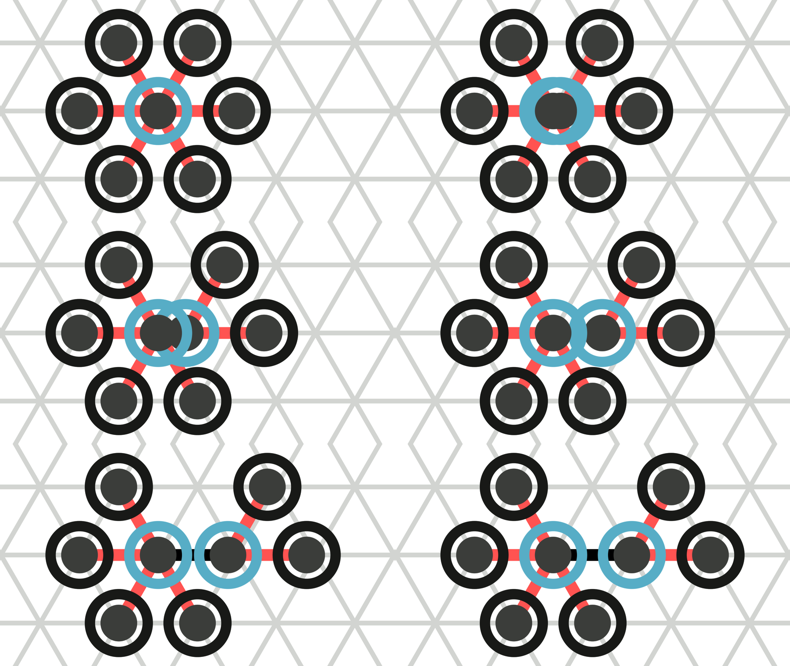
A contracted amoebot may expand on one of the axes as follows (see Figure 2a). At \(t = 0\), the amoebot splits its single node into two nodes, adds a bond between them, and assigns each of its other incident bonds to one of the resulting nodes. Then, the amoebot uniformly extends the length of the new bond. At \(t \in [0,1]\), that bond has a length of \(t\). In the process, the incident bonds do not change their orientations or lengths.
An expanded amoebot may contract into a single node as follows (see Figure 2b). The amoebot uniformly reduces the length of the bond between its endpoints. At \(t \in [0,1]\), the bond has a length of \(1 - t\). At \(t = 1\), the amoebot removes that bond, fuses its endpoints into a single node, and assigns all of its other incident bonds to the resulting node. In the process, the incident bonds do not change their orientations or lengths. We remove duplicates of bonds if any occur (see Figure 2c).
Furthermore, a contracted amoebot \(c\) occupying a node \(u\) and an expanded amoebot \(e\) occupying nodes \(v\) and \(w\) may perform a handover if there is a bond \(b\) between \(u\) and \(v\) (see Figure 2d). A handover consists of the following three phases. All following contractions and expansions happen at twice the speed. In the first phase (\(t \in [0, 0.5]\)), \(c\) expands on the axis through \(u\) and \(v\). Thereby, it assigns \(b\) to the node towards \(v\) and all other bonds to the other node. Let \(v'\) denote the node towards \(v\) (in the simulator, this is \(c\)'s head). At the same time, we contract bond \(b\). In the second phase (\(t = 0.5\)), \(e\) passes all bonds incident to \(v\) to \(c\) that assigns them to node \(v'\). Additionally, we adjust the orientation of \(b\) to the orientation of \(e\). In the third phase (\(t \in [0.5, 1]\)), \(e\) contracts into a single node. At the same time, we expand \(b\). Thereby, \(b\) assigns all bonds to the node towards \(v'\). Overall, note that handovers work equivalently to the handovers in the original amoebot model.


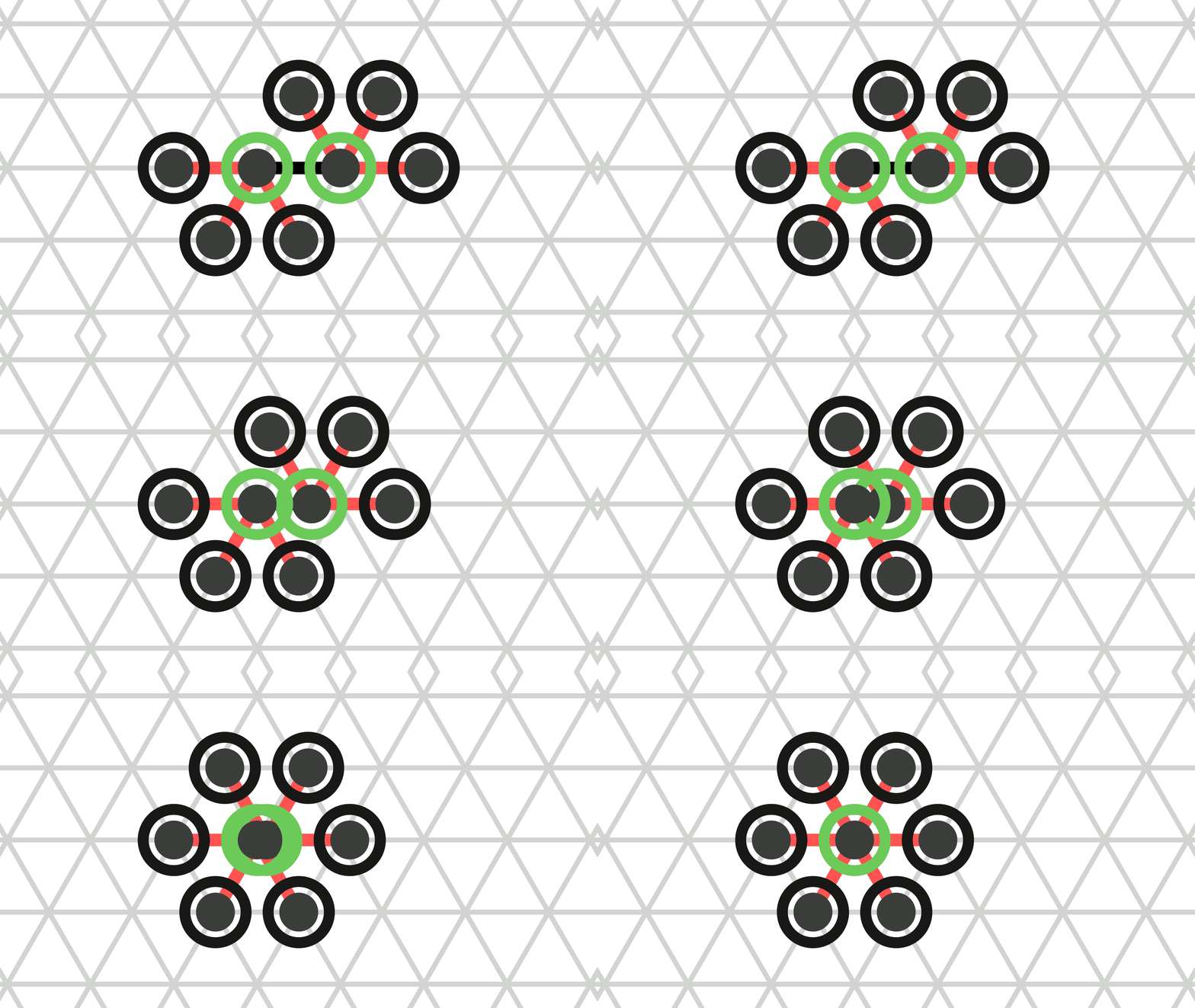
The amoebots may not be able to perform their movements. We distinguish between two cases. First, the amoebots cannot perform their movements while maintaining their relative positions (see Figure 3). We call that a structural conflict.
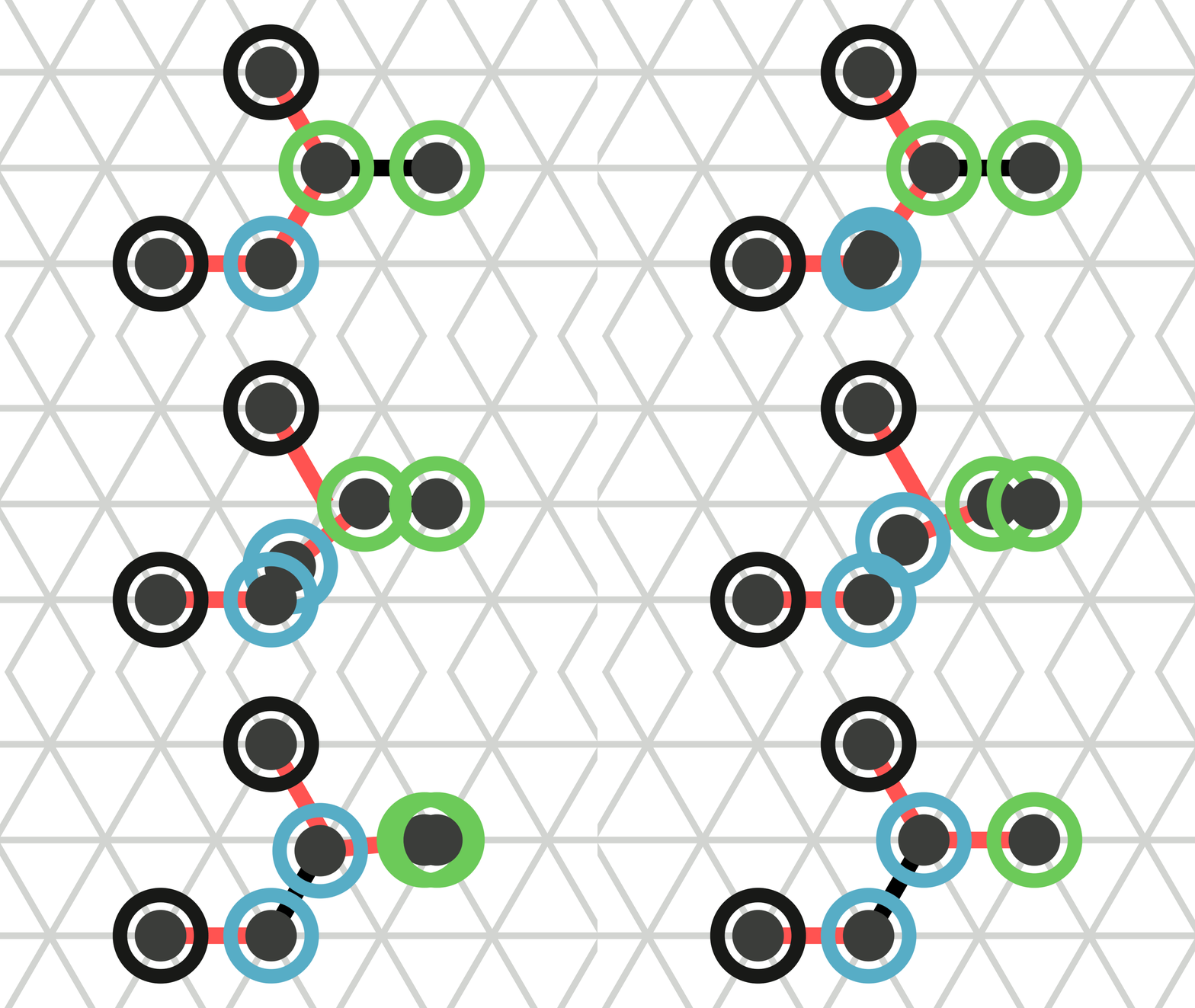
Second, parts of the structure collide into each other. More precisely, a collision occurs if there is a \(t \in [0, 1]\) such that two bonds intersect at some point that is not incident to both bonds (see Figure 4). In particular, note that an expanded amoebot cannot contract if it has two incident bonds to the same node even if the amoebot occupying that node expands at the same time without causing a collision (see Figure 2e).
Whenever either a structural conflict or a collision occurs, the amoebot structure transitions into an undefined state such that we become unable to make any statements about the structure.
Note
In the simulator, any structural conflict leads to an exception that resets the round simulation. Collisions are currently not checked.
Otherwise, at \(t = 1\), we obtain a graph \(G_M = (S, E_M)\) that can be mapped on the triangular grid \(G_\Delta\) (see Figure 3). Since \(G_R\) is connected, the mapping of \(G_M\) is unique except for translations (if one exists). We choose any mapping as our next amoebot structure. Afterwards, the amoebots reestablish all possible bonds.
We assume that the joint movements are performed within look-compute-move cycles. In the look phase, each amoebot observes its neighborhood and receives beeps on its partition sets. In the compute phase, each amoebot may perform computations, change its state, and decide the actions to perform in the next phase (i.e., which bonds to release, and which movement to perform). In the move phase, each amoebot may release an arbitrary subset of its incident bonds, and perform a movement.
Adaptation in the Simulator


 The animations above show the example movements from Figure 2 a, b, and d as they are animated by the simulator.
The joint movements extension is implemented by AmoebotSim 2.0, but some changes were made to make it easier to work with. First, we introduced an anchor particle: One amoebot is marked as the anchor of the structure so that the mapping of the final structure \(G_M\) to the grid \(G_\Delta\) is unique. We choose the mapping that corresponds to no translation relative to the anchor.
Next, we added a mechanism so that expanding amoebotss can explicitly define their assignment of bonds. In the model description above, it says "(...) the amoebot splits its single node into two nodes, adds a bond between them, and assigns each of its other incident bonds to one of the resulting nodes." We define that the head of the expanding amoebot is the part that moves onto the new node. Similar to releasing bonds, an expanding amoebot is now able to mark bonds that should be assigned to its head. All remaining incident bonds are automatically assigned to its tail. Note that of the two bonds that coincide with the expansion axis, one is always marked and one can never be marked.
Finally, perhaps the most significant change regards the structure of amoebot activations. The model description above does not state how exactly the construction of circuits and the transmission of beeps are incorporated into the activation model. For the simulator, we decided to split the movement and the communication into two distinct phases. The first phase is a look-compute-move cycle as explained above: The amoebots can alter their own state and schedule movements based on a snapshot of the current system state. We call this the movement phase. After the movements comes the second phase, which is a look-compute-beep cycle. This phase is identical to the movement phase except that instead of scheduling movements, the amoebots alter their pin configurations and send beeps and messages. We call this the beep phase.
All of these changes are explained in more detail on the Model Reference pages, in particular, the Round Simulation and the Bonds and Joint Movements pages.